- (801) 210-1303
- [email protected]
- Weekdays 9am - 5pm MST
The first step to securing funding is building a plan for your program. Let us help you get started.
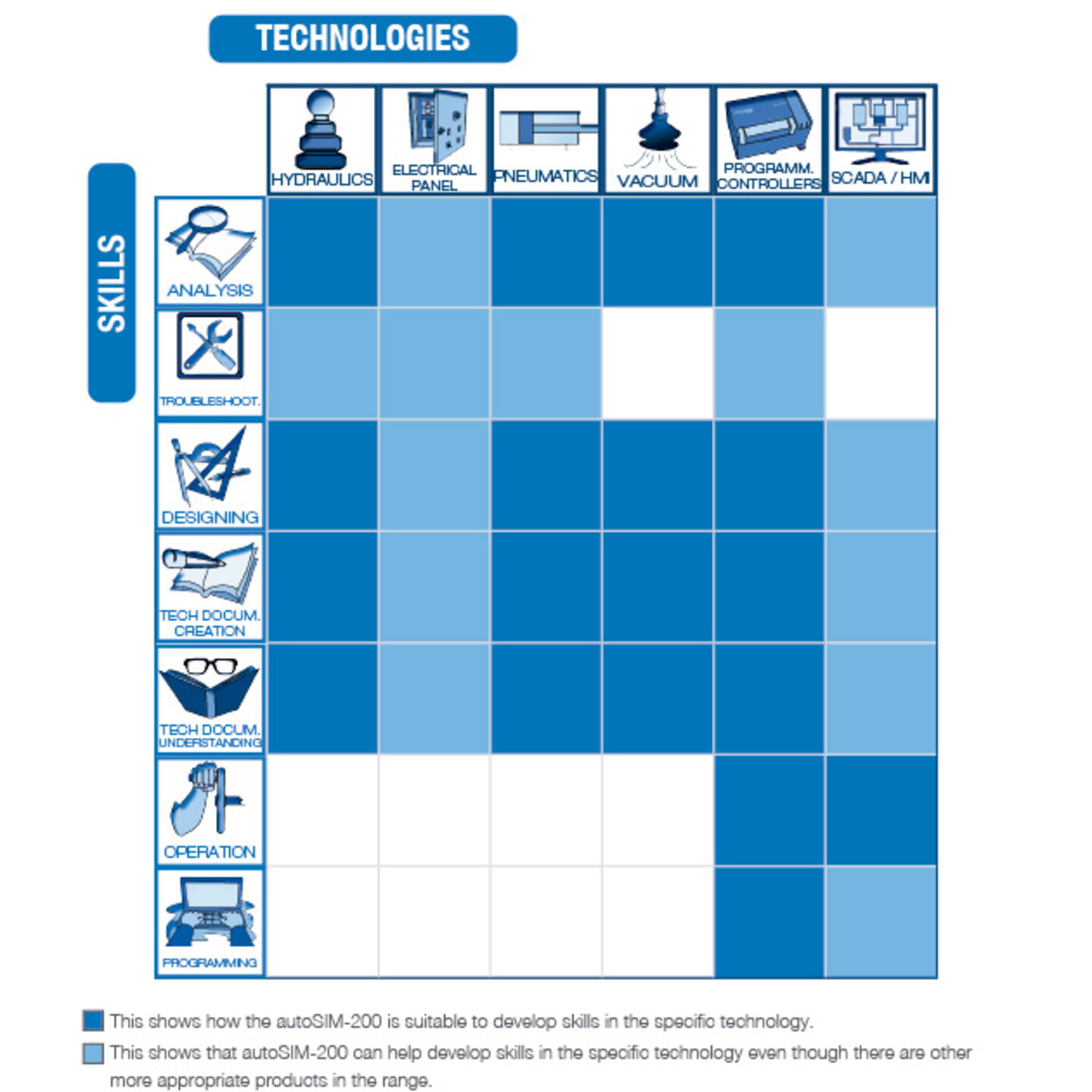
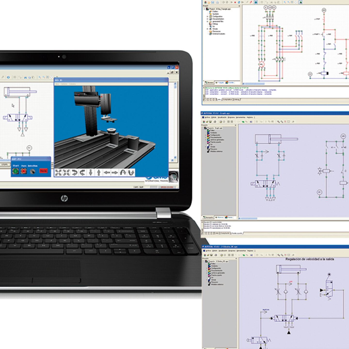
The autoSIM-200 simulation software is our all-encompassing digital software from SMC for creating, simulating, and visualizing Electrical, Pneumatic, Hydraulic and Control Circuits.
With autoSIM-200, it is possible to carry out dynamic, multi-color simulations using pneumatic, electro-pneumatic, hydraulic, electro-hydraulic, electrical and electronic circuits. A Library stocked with Industrial Component are displayed by means of drop-down menus, showing individual standardized symbols, including conventional and proportional pneumatic and hydraulic valves.
autoSIM-200 can be used to create Grafcet diagrams, Ladder, Logigramme (logic gates) and function blocks with structured text. By running the simulation, it is possible to monitor and control the application step by step.
autoSIM 2D provides students with practical lab activities and proposed circuit simulations for SMC Training Systems.
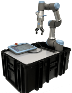
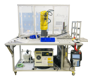
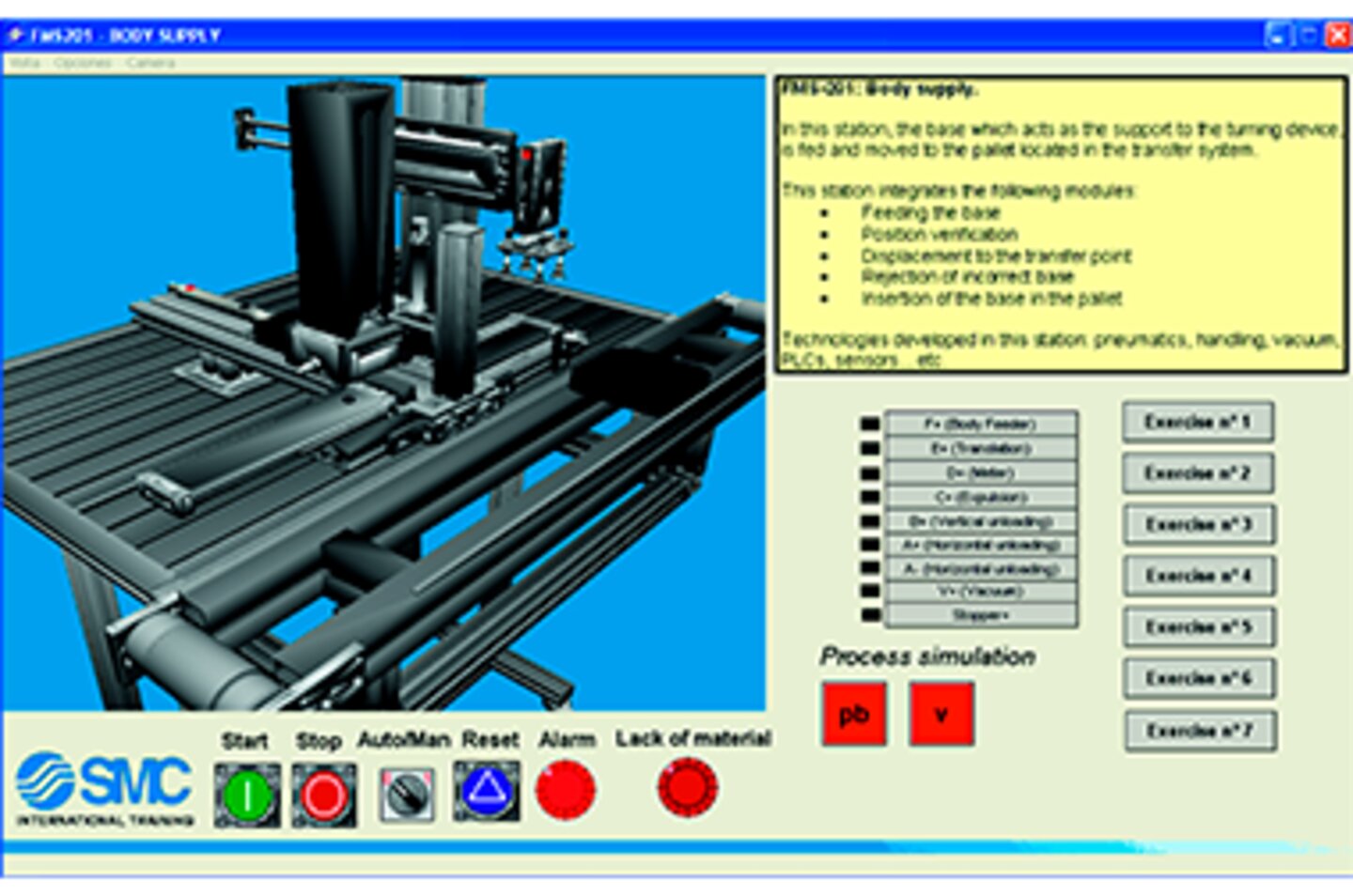
autoSIM 3D delivers students the 3D virtual models of SMC mechatronics training systems for programming, controlling, and monitoring automated processes.
SMC’s autoSIM software allows 2D and 3D simulation of industrial automation applications that incorporate pneumatic, electro-pneumatic, hydraulic, electro-hydraulic, electrical and electronic technology simultaneously through graphics.
SIMULATION:
PROGRAMMING:
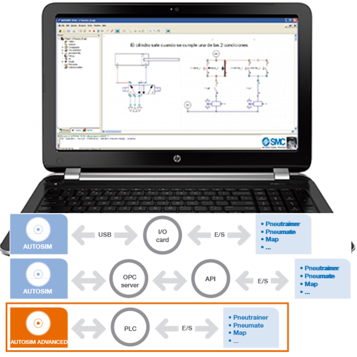
CONNECTING THE APPLICATION WITH THE OUTSIDE WORLD:
This connection can be established through:
LIBRARIES:
SIMULATION
PROGRAMMING
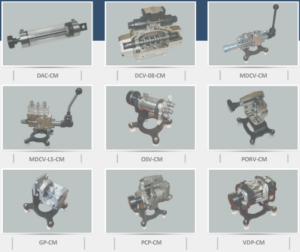
3D Simulations of the following: